Because of a downed tree during a storm I had to put up new antennas. I had limited space so waned to go to a multi-band antenna. From previous attempts to adjust a multi-band with just a standard SWR meter, I knew that I needed something that can scan a large frequency range at one time. I found several web sites with information on different types of antenna analyzers, but one by Beric Dunn (K6BEZ )looked like it would be the easiest to build.
Corrected Link
http://www.hamstack.com/project_antenna_analyzer.html
He has versions for both PIC and Arduino based projects. I had just finished a VFO using a SI5351 and had working code to control it, I wanted to try using that instead of the AD9850 module he used. I bread boarded the bridge circuit and connected the 5351 VFO after adding a simple LC low-pass filter. Then modified the antenna analyzer code to incorporate the 5351 code I had written. Using the PC based software from Beric, it looked like I was getting valid data when connected to different resistive loads. Connecting to a simple dipole antenna the results also looked like what I would expect. I used this to help tune a G7FEK antenna I put up.
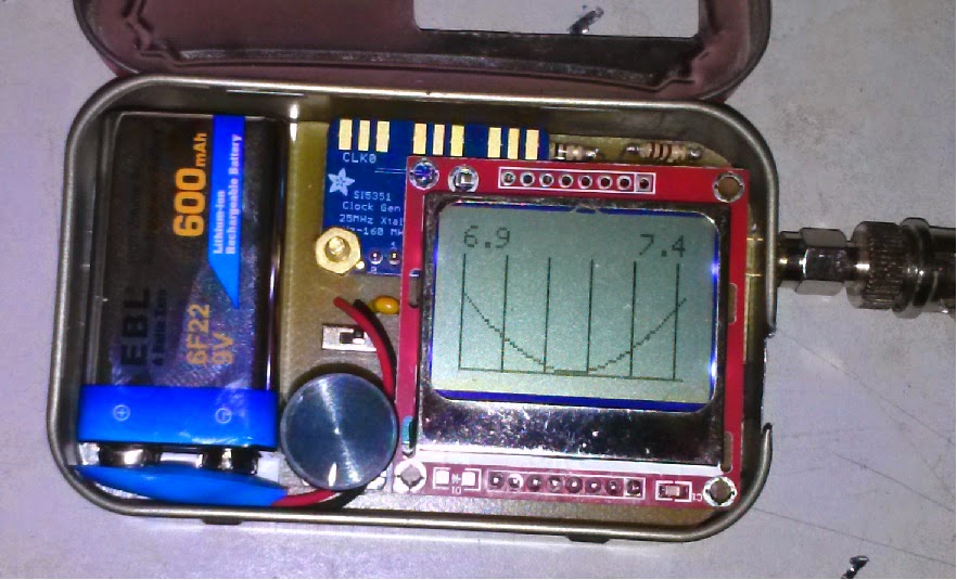
Since The Nokia display and driver software I used was capable of doing graphics, I re-worked the code to display the sweep on the screen. Later I decided to store the SWR values in an array, and wrote code to scroll through the completed sweep using the rotary encoder. Also used the push-button on the encoder to enable band switching.
![]() When everything looked like it was working, I designed and etched a small circuit board. Because of the small size of the Adafrit SI5351 module I used, I was able to put everything in an Altoids tin.
When everything looked like it was working, I designed and etched a small circuit board. Because of the small size of the Adafrit SI5351 module I used, I was able to put everything in an Altoids tin.
![]()
I wondered if harmonics from the square-wave output of the 5351 would cause problems in the results. I decided to build a version using and AD9850, which had a sine-wave output. Also switched to a color TFT display. Doing comparison tests I found very little difference in the results I was getting. Because of the size of the 9850 module and power requirements I was not able to to get it and the battery to fit in the Altoids tin. But stacking two of them, one for the board, and one for the battery pack worked out.
Although both versions were usable I am looking at replacing the simple resistive bridge in the original design and going to a 3 voltage scheme to also compute impedance values.
I have a slightly larger TFT display that should work well to display the additional information. Will update when I get around to that project.
Corrected Link
http://www.hamstack.com/project_antenna_analyzer.html
He has versions for both PIC and Arduino based projects. I had just finished a VFO using a SI5351 and had working code to control it, I wanted to try using that instead of the AD9850 module he used. I bread boarded the bridge circuit and connected the 5351 VFO after adding a simple LC low-pass filter. Then modified the antenna analyzer code to incorporate the 5351 code I had written. Using the PC based software from Beric, it looked like I was getting valid data when connected to different resistive loads. Connecting to a simple dipole antenna the results also looked like what I would expect. I used this to help tune a G7FEK antenna I put up.
Since The Nokia display and driver software I used was capable of doing graphics, I re-worked the code to display the sweep on the screen. Later I decided to store the SWR values in an array, and wrote code to scroll through the completed sweep using the rotary encoder. Also used the push-button on the encoder to enable band switching.
 When everything looked like it was working, I designed and etched a small circuit board. Because of the small size of the Adafrit SI5351 module I used, I was able to put everything in an Altoids tin.
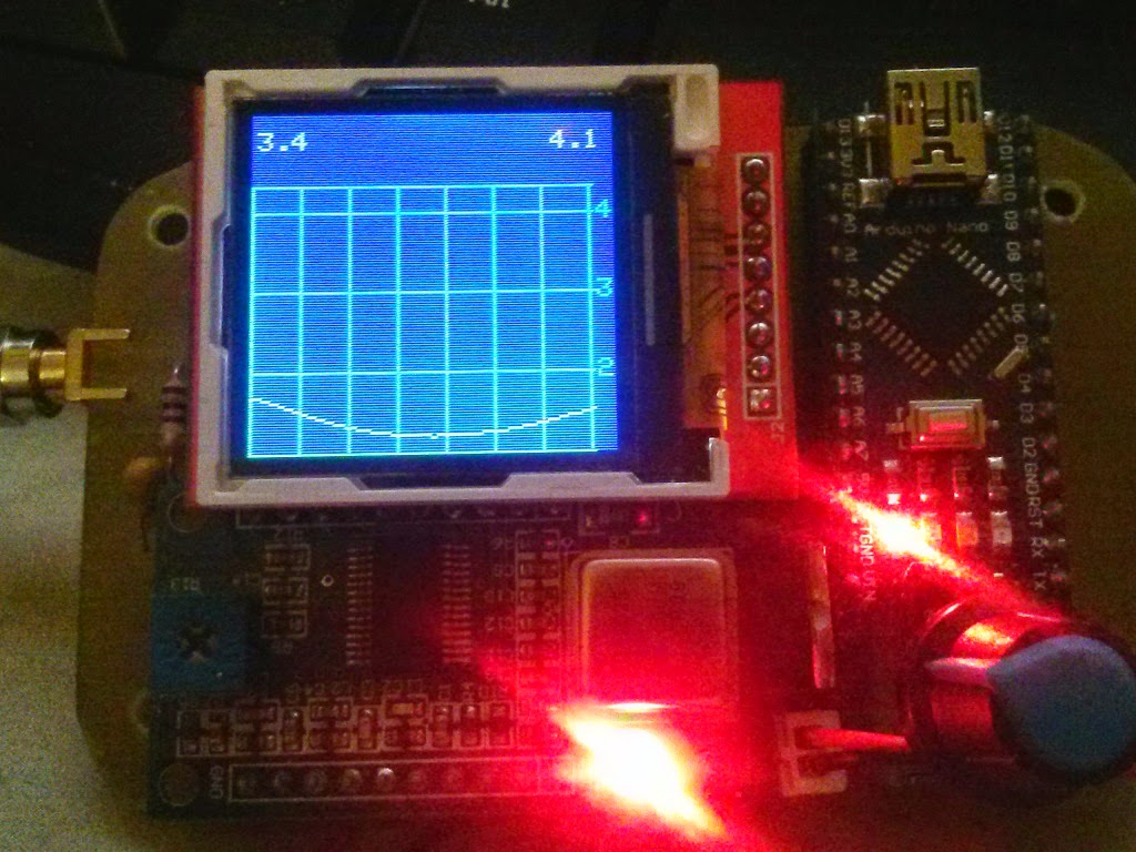
I wondered if harmonics from the square-wave output of the 5351 would cause problems in the results. I decided to build a version using and AD9850, which had a sine-wave output. Also switched to a color TFT display. Doing comparison tests I found very little difference in the results I was getting. Because of the size of the 9850 module and power requirements I was not able to to get it and the battery to fit in the Altoids tin. But stacking two of them, one for the board, and one for the battery pack worked out.
Although both versions were usable I am looking at replacing the simple resistive bridge in the original design and going to a 3 voltage scheme to also compute impedance values.
I have a slightly larger TFT display that should work well to display the additional information. Will update when I get around to that project.